Detector Configuration in COMICS
| Manufacturer | Santa Barbara Research Center, Raytheon |
| Model | 320x240 Si:As IBC High-Background Astronomy IR Focal Plane Array |
| CRC-774 Silicon Cryo-CMOS Read-Out Integrated Circuit interconnected to a backside-illuminated Si:As IBS photodetector | |
| Operating Temperature (COMICS) | 8.00K at the detector mounts |
| Format | 320 x 240 pixels |
| Pixel Size | 50 micron x 50 micron |
| Number of Outputs | 16 channel |
| Power Dissipation | about 80mW (measured) |
| Readout Mode | integrate-while-read-mode |
| Multiplexers (MUXs) | row MUX circuit, row-reset MUX circuit, column MUX circuit |
| Source Followers | 1 on each unit cell |
| 2 on each Column Clamp, Source Follower, Sample/Hold, Source Follower | |
| 1 on each output multiplexer | |
| Sample/Hold Circuit | 320 (320 pixel, that is one row, can be sampled/held at once) |
Experimental Performances
- Basic Parameters (at 8K)
- Conversion Factor
-
Conversion factors measured in the laboratory is 140 e-/ADU for
the imaging detector, and 690 and 1100 e-/ADU for two spectroscopic
detectors at 8K. However, when we measured amplifying rate of
multiplexer assuming some condensor capacities on it as designed
values, we obtained 2410e-/ADU for a calculated conversion factor. The large
difference between these two kind of values seem to be caused by
unsusually large excess noises at laboratory measurement for the
formers. So, we just write the parameter values for detectors
not in e- but in ADU below.
- Dark Current, Readout Noises, and Quantum Efficiencies
Imaging Spectroscopy Readout noise 2.2 ADU 2 ADU Dark current 1900 ADU/s 30ADU/s or negligible Quantum Efficiency 1 10 % 20 % Quantum Efficiency 2 40 % 40 % NOTES:
QE 1 is the value when measured conversion factors were used.
QE 2 is the value when calculated conversion factors were used.
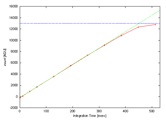
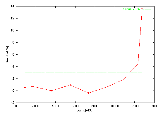
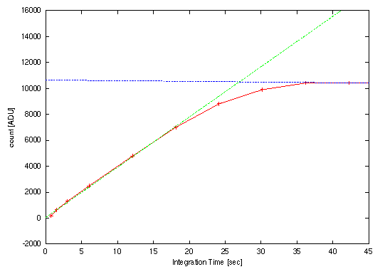
- Linearity and Saturation Level
-
See here.
- Fringes
-
In the intermediate-resolution spectroscopy,
the fringe patterns of intensity like Fig. 1 are observed.
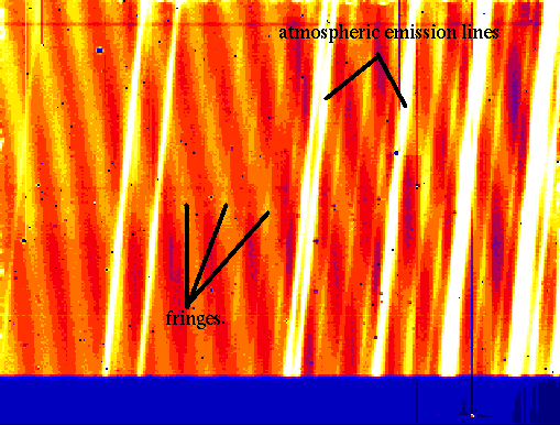
Fig. 1. Dark-subtracted image of intermediate-resolution spectroscopy in the N-band. Horizontal axis is for wavelength axis and vertical one is roughly for spatial axis.The directions and intervals of the fringes are different between the detectors. In addition, the direction is independent of the incident wavelengths, while the intervals increase as the incident wavelengths. The fringes seem to be due to interference at two surfaces of high resistivity silicon substrate of the detector, whose thickness is 500 micron and whose refractive index is about 3.417 at 12micron. This leads to efficiency dependent on the wavelengths and the position on the detectors. If the wavelength/pixel relation reproduce exactly between frames for objects, calibration stars, and flat, the fringes will be cancelled by flat-fileding and the correction for atmospheric transmission by calibration stars. However, both of accuracy of positional reproductivity and rigidity are not high enough now. One must take four kinds of frames (object frames, flat for them, calibration star frames, and flat for them) at the same position angles of the instrument rotator and the same elevations as possible.
- Drooping Effects for data before Sep. 2000
This section is only for users before Sep. 2000. This problem was fixed by upgrading driving clock patterns after Dec. 2000. So, users after that go to the next section.
-
When the detectors are used with old clock patterns which was
proposed by SBRC, they show 'drooping effects': that is a phenomenon
that the pixel output values become non-linear and/or are affected by
their surrounding pixels when strong light enters. Cross talk between
pixels in a narrow sense is not included in this effects. A similar
phenomenon was reported for the detectors of SIRTF/IRC (Van Cleve, J;see
here).
In the case of the COMICS detectors, the drooping effects are classified
into three types. Fig. 2. shows how all types of the drooping
are seen in the obtained images.
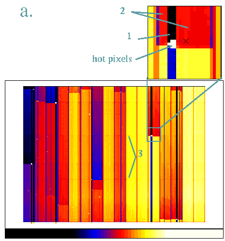
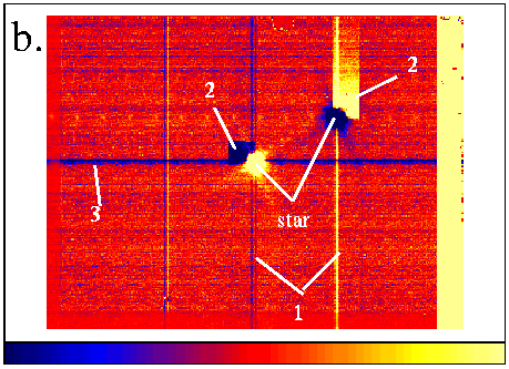
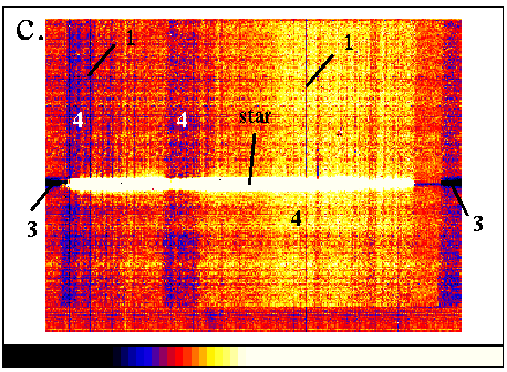
Fig. 2. Drooping phenomena. (a) Dark image. (b) Star image after chop subtraction (star image in main-beam is blue and that in offset-beam is yellow). (c) Star spectrum after chop subtraction.
The numbers in the figures are suggest the type of drooping stated below. 4 is residuals of sky line emissions after subtraction.The first is output level shifts along columns of detectors. When a certain column is examined, count for pixels after a pixel where a high count was read out decrease compared to those for pixels before the pixel of high count. This phenomenon is caused by hot pixels and a bright objects. If there is an isolated hot pixel, counts along the column take the minimum value two pixels after the hot pixel and then return to the original level exponentially with a time constant of about 10msec. The maximum shift values fluctuate by frames and cannot predict exactly. These shifts are caused by a drop of reset level for columns of detector readout multiplexers (MUX) after a strong current was read out.
When the level shifts along columns are large, they affect to the columns in the same channel and cause the second type drooping effect: the level shifts within channels. The counts of pixels read out after the high count pixel drop down (these pixels must belong to the same channel of the high count pixel). The shifts are almost constant along the row. The levels return to the original level along columns with the time constant of about 10msec.
The third is a drop of zero level, appearing for all pixels of the same rows of the whole detector. Their shift values are estimated to be constant along rows in most cases. This is caused by a group of high count pixels, such as a group of hot pixels, an image of bright objects, and a bright spectrum. This phenomenon will occur if a reset level for rows of the MUXs drops.
- Conversion Factor