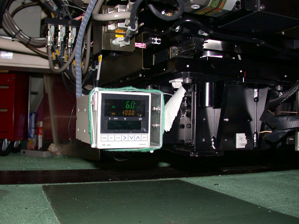
If the CCD temperature is close to the ambient temperature (~5C), proceed to the followings.
[FOCAS INSIDE]
|--------------------|
|Dewar ==T connector==|== inner valve (yellow) == long tube == T connector == ion pump -- controller
| || | ||
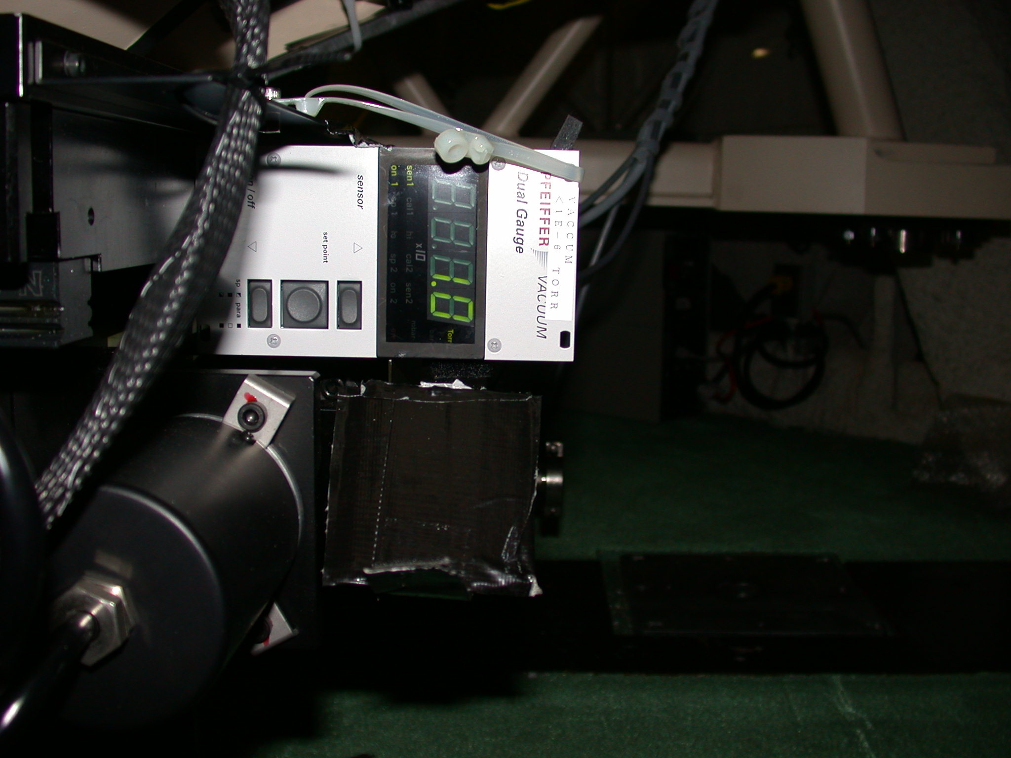
| Vacuum gauge | outer valve (white) == external pump
|-----------|--------|
|
Vacuum gauge display
If the CCD temperature is < 0 C, you cannot do pumping.
If the CCD temperature is close to the ambient temperature (~5C), proceed to the followings.
The vacuum level should be 1e-1 ~ 1 torr (the value may vary according to the previous usage and conditions).
If the vacuum level is 1e-3 torr or less, you cannot do pumping.
There are two valves. Inner one (closer to the CCD chamber inside the FOCAS at rear side at Cs) and the outer one (at front/IR side).
Left: Inner valve (a cylinder with a yellow screw), Right: Outer valve (recently replaced to the white one. This picture shows the old one.)
Close the inner one if it was open. Screw the yellow portion of the valve completely to the end. Screw it gently.
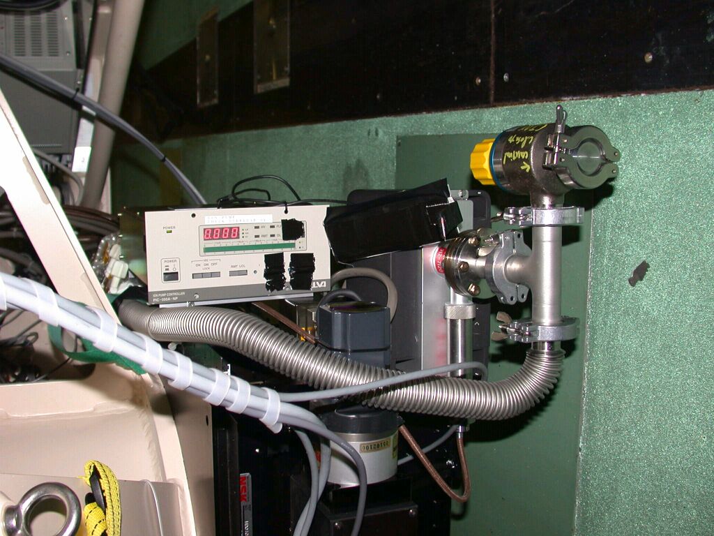
Use a portable VARIAN pump stored at the 3rd floor of the control building.
Make sure that both o-ring and flanges are clean of oil/debris.
Clean them with alcohol and kim wipe if necessary, and grease them up. Use as little vacuum grease as possible. Excess grease often works to worsen the vacuum.Fasten the vacuum clump securely
Make sure that the release valve (a small (~1 inch size) screw at the side wall of the turbo pump) is closed.
Press START button on the pump controller.
Wait for a sign "normal operation 56K" shows up on the controller.
To avoid sudden change of the vacuum level in the CCD chamber, open it very slowly while checking the vacuum gauge. Stop opening the valve if the vacuum level rises in a short time scale (~several seconds) and wait for a while (~30 seconds) until it stops rising.
Open it completely at the end.
- Set it to local mode (LCL)
- Switch a main power of the pump controller on.
- Switch a HV (high voltage) power on. Do not push HV power on (lock). Switch it back off in 1 second.
- Check the vacuum gauge. Due to the out gas from the ion pump, the vacuum quickly rises up. Wait for a minute until the vacuum gets lower than the level at the start up.
- Switch the HV power back on again, and switch it back off in 2 seconds. Wait for the pumping out of the out gas by the external pump.
- Repeats the above sequence (HV on, off, wait) several ~ 10 times until the out gas is almost negligible while the HV is on. The number of iterations required may vary according to the vacuum level at the start up of this sequence.
- Check if the vacuum level is lower than the level at the beginning of the ion pump start up at the end of the sequence.
Now the vacuum is maintained by only the ion pump. Make sure that the vacuum level is almost constant even after closing the valve. If it raises slowly, there must be something wrong (i.e., leak).
Stop the external pump by pushing the button on the panel of the pump.
Open the release valve very (a small screw) very slowly. Take at least one minute to open the screw completely. After the release, do not forget to close it.
Cover the flanges with caps and clumps.
After checking everything is OK, the ion-pump controller should be set to be Remote.
Call SA (he may be at the control room in the control building, or even at Hilo/HP). This is a quick three step procedure.
- Set it remote on the controller front panel. The ion pump will be temporarily OFF. All the LEDs (except for the main power indicator) will go off.
- Ask SA to re-activate it remotely. He will turn it back ON using the remote control software.
- Check the front panel to see the ion pump conditions. If all LEDs go back on, it is OK.