MOIRCS MDP Manual [English]
MOIRCS Mask Design Program Manual
Chihiro Tokoku
2016-08-09
(revised by Ichi Tanaka: 2024-08-01)
0. Introduction 1. Preparation 2. MDP Startup 3. Mask Design 4. Save the images 5. Submit the results 6. Acknowledgment
0. Introduction
"MDP" is an abbreviation of "Mask Design Program". This software provides a graphical interface for interactive designing of the custom slit mask of the MOIRCS Multi-Object Spectroscopy "MOS" mode observation, and will be used by open-use observers.
This document describes the usage of the MDP program.
1. Preparation
1.0 System requirement
- Computers with Linux/Unix or related OS is recommended. We are not testing the function for Mac or Windows PC.
- Our MDP program runs on the IDL Virtual Machine (IDL VM) environment. The IDL VM is a free software and runs on the various OS without IDL. Please download and install a most recent IDL VM to your Linux/Unix computer. IDL VM can be downloaded from the following web site.
IDL Virtual Machine
Note that the IDL VM may fail if the version of your Linux is too old or too new. Please ask the 13Harris Support Desk about the failure. - Download the current MDP program file ( wmdp_moircs.sav ) from the download website (updated Feb 2023).
1.1 Preparing the images
You will need a FITS image of your target field to do the mask design over the MDP program. You can use any FITS images if it is prepared without the optical distortionand in tangential projection (CTYPE1 = 'RA---TAN', CTYPE2 = 'DEC--TAN'), and its pixel scale is accurately adjusted to 0.1170"/pix. We recommend to use the Pan-STARRS 1 (PS1) image (all-sky data from Maunakea is available from the image cut-out service on their archive), or the properly reduced data by the HSC-SSP, Hubble Space Telescope, MOIRCS, FOCAS etc, after converting the pixel scale. However, the porper motion of the stars may introduce the critical error if it is too old. Be very careful when use the data older than 10 years.
If necessary, you may ask (on the proposal) taking some images of your MOS fields for mask design ("preimaging obs") on 2 to 4 months before your MOS observation. Please read the document about the detail of how to prepare for the preimaging observation.
Note:
Here is a few caution on the HSC data for preimage. If you cut out the preimage data from the edge of the SHC field of view, it may be somewhat less accurate. Re-calibrating by the PS1 data may help. Another caution is the saturation of the bright stars in HSC data. The accracy of the centering of the stars will go poor. You should avoid to use such stars for the alignment / astrometry of your own data for mask design.
HST data generally works great for mask design after converting the pixel scale. FOCAS data is also okay but note that the imaging data is usually flipped in X direction. For other FITS data in general, please make sure to remove the optical distortion and the error on the wcs. It's user's responsibility. You may consult to the primary SA for double check.
1.2 Target selection
We assume you already have a deep imaging data of your proposed fields for picking your targets. The main purpose of the preimage described above is the astromentric reference. What you do first is to aligh your deep imaginga data to the PS1 imaging data etc as closely as possible, then use the aligned deep image to pick up targets . When you make the catalog based on the xy coordinate of the aligned image, make sure to measure the position in sub-pixel accuracy.
Some IDL users may measure the XY position of targets on the software. We note that our XY coordinate system assume the origin is (1, 1), though the IDL generic coordinate system starts from (0, 0). The MDP software handles this difference internally so don't confuse this.
1.3 Creating *.mdp file
Make your input file for the MDP program (.mdp file). The .mdp file is a text file that contains the information on the slit position, width and length of the slit (and angle in special case) etc. You can manually prepare the file before running the mdp program. Or you can make the mdp interactively within the MDP program. We recommend to prepare the target coordinates separately and use it for the mdp file, because the accuracy of the position measurement on the wmdp software may occasionaly be poor.
The format of the mdp file is as follows.
Obj1-X[PIX] Obj1-Y[PIX] Length1[PIX] Width1[PIX] Angle1[DEG] 1 B, comments...
Obj2-X[PIX] Obj2-Y[PIX] Length2[PIX] Width2[PIX] Angle2[DEG] 1 B, comments...
Obj3-X[PIX] Obj3-Y[PIX] Length3[PIX] Width3[PIX] Angle3[DEG] 1 B, comments...
.
.In addition to the slit, information about the "alignment stars" that is used as a reference to properly align the slit with the object should also be specified in this file. The only important formatting is the XY coordinates (in pixels) of the star and the size of the hole (30x30 pixels is recommended). Please leave the rest of the string untouched.
Star1-X[PIX] Star1-Y[PIX] 30(HoleSize)[PIX] 30(HoleSize)[PIX] 0 0 C, Alignment Hole
Star2-X[PIX] Star2-Y[PIX] 30(HoleSize)[PIX] 30(HoleSize)[PIX] 0 0 C, Alignment Hole
Star3-X[PIX] Star3-Y[PIX] 30(HoleSize)[PIX] 30(HoleSize)[PIX] 0 0 C, Alignment Hole
.
.[example]
1646.0900 2525.9802 170.0000 8.0000 0.0000 1.0000 B, Object-1
1929.3048 2935.7109 30 30 0.0000 0.0000 C, Alignment Hole
- The form must be one object per line.
- In the MDP program, the XY coordinate origin is (1, 1). We note this because the coordinate system in IDL usually starts from (0, 0). Users should use the general XY coordinate system starting from (1, 1). Please be careful when creating *.mdp files by measuring the coordinates of the target objects using the other IDL softwares.
- Slit/Hole shape is specified by "B," for box=slit or "C," for circular=alignment hole.
- The value "1" before "B" originally indicates the priority (for auto design function). But currently the function is not working so it is ignored. You can use the column for your record of the priority (use integer!) if it is convenient.
- All remaining characters after the shape parameter (B, or C, ) are regarded as a comment. But please put a space after ",".
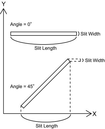
- [FYI for special use] Slit angle is defined in the detector coordinates (not in the SKY coordinates) and is expressed in degree whose positive/negative direction is in a normal geometry (counter-clockwise). For example, Angle = 0 for normal slit (perpendicular to the dispersion axis), and 45 degree for the tilted slit whose right side is raised by 45 degree in the MDP program(Note1).
-
For the alignment stars, you should put the word "Alignment Hole" in the comment fields (but you can add words after it). Please use the diameter of 30 pixels (= about 3.5" diameter) for alignment hole. Don't change the value as much as possible.
Note 1:If you want to put the tilted slits on your mask, you will need a special care for the design. As we do the nodding observation (the A-B dither) for sky subtraction, your targets on single tilted slit will drop off from the slit. To avold it and to observe in maximum effeciency, you can put the identical tilted slits in the same separation as the nod throw length along the spatial direciton synmetrically to the pointing position, in order to keep the target always on either of these tilted slits during the nod.
In case of the tilted slit, the slit width defined here (Width#) means the slit width projected into the dispersion direction (to keep the effective spectral resolution the same for all slits with various tilt angle), and the slit length (Length#) means the projected length on the X coordinate. Be careful.Those who wants to make tilted slit mask design should first contact to the primary SA to avoid any potential mistakes.
2. MDP start-up
- Type "idl -vm=wmdp_moircs.sav" in your computer.
- Click IDL logo window, and the MDP program window shows up.
- Select [ File ] - [ Read FITS image ] from the pull-down menu, and select a mosaicked FITS image in a pop-up window.
- A FITS image will show up when you click "Auto-Intensity Scale". You can change the display range by "Change Intensity Scale".
-
Select [ File ] - [ Read MDP file ], and select a MDP file you created as shown above in "Input MDP file" window.
If you do not have a MDP file, just push "Cancel" button for interactive mask design for all slits. In this case, one dummy slit will be set.
-
Select [ Option ] - [ Grism select ], and select an appropriate grism in "Grism Selection" window.
- Click on "Redraw" or "Draw Slit" buttons to see the image and the slits.
- Now you are ready to start editing the masks.
2.1 Explanation of the Main MDP window
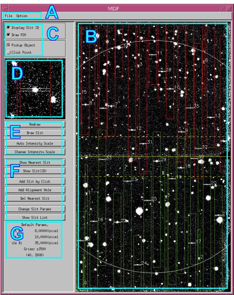
Click for detail.
-
Pull-down menus
- File : Tasks for file I/O.
- Option : Grism selection and the parameters setting for slits and holes, etc. -
Main window
Your FITS image is shown in the detector coordinates (pixel). Currently the wcs use is not supported.
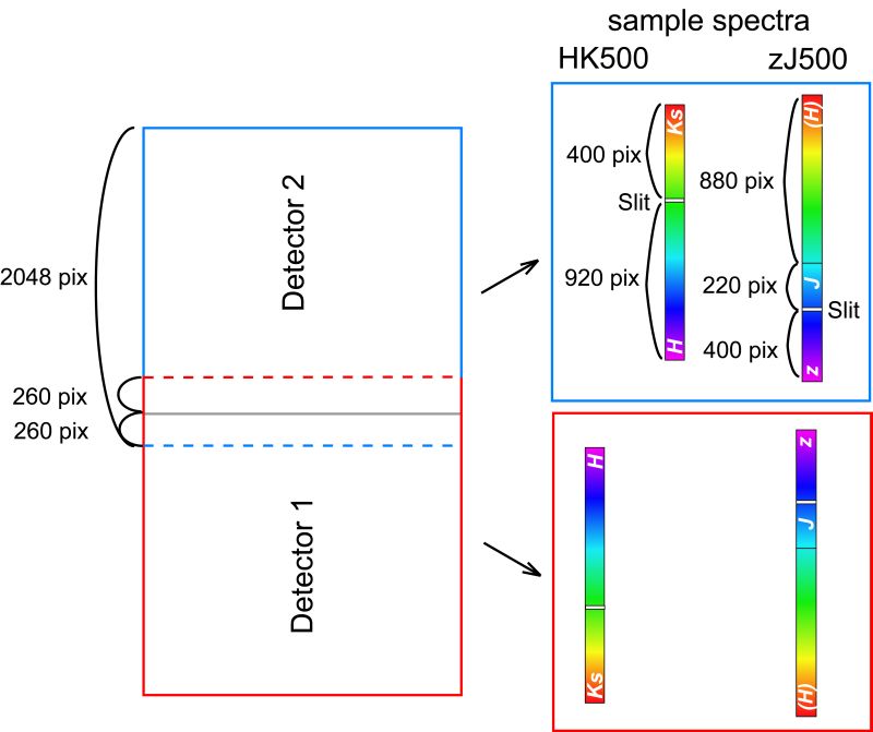
Wavelength is in vertical direction. See also this figure(Note 2).
upper detector ( detector 2 ) : upper=redder, lower = bluer)
lower detector ( detector 1 ) : upper=bluer, lower = redder)A rough full field of view (7' x 4') is shown. Not that the edge positions are not exact(Note 3).
Items shown in above figure:
- Main FITS image display (entire view of the image at reduced size)
- Slit marker (small elongated rectangle on targets)
- Spectra marker (long rectangle elongated vertically: the dashed-lines are added in 2023 for every 400A or 500A interval from the straight-through wavelength)
- Slit ID number (small number just right of the slit markers)
- Slits available area (large circle showing the available area for slit cutting)
- Center line of FOV (Continuous line at the center: this is the "mosaic boundary" of two channels, and we avoid cutting slits near here.)
- Edge line of detectors (Dashed lines upper and lower of the center line(Note 2). Upper one is a edge line of the detector 1 and lower one is that of the detector 2.) -
Mode selection switches
- Object pick-up mode (apply Gaussian fitting on the image around the clicked position, or simply adopt the clicked position as a final position)
- FOV circle display switch
- "Slit ID display" switch does not work, and the slit IDs are always shown on the main display. - Zoom image display
Display for zoomed (non-reduced) FITS image around the selected region for slit review. This display is also used for object selection by mouse (see below). - Buttons for controlling the image display
Display intensity adjustment, image redraw button, etc. -
Buttons for slit editing
Buttons for editing slits and alignment holes. -
Information panel
Panel showing default slit parameters and current mouse positions.
Note 2:
Note that even if the green boxes and red boxes overlap with each other on the mdp window, in the actual data they do not. MOIRCS consists of twin optics & detector system. The green (red) spectra beyond the upper (lower) horizontal dashed line will just drop off from the edge of the channel-1 (2) detector.
Note 3:
As of 2016, it is known that the drawn FOV is too wide. The actual left edge line comes about 50 pixels inwards (to the right). The right edge is relatively accurate. → Fixed in Feb 2023!
3. Mask Design
In the followings, detailed procedures on how to design the mask interactively is described. We recommend to design your masks following the order as we show below. Of course, you may repeat any tasks until you are satisfied with your design.
3.0 Notice: wmdp_moircs.sav is EASY TO CRASH!
It is known that unfortunately the wmdp_moircs.sav software is quite easy to crash. Canceling any action could result in the crash event in some environment. We strongly recommend to try saving the mdp fine under work as frequently as possible to avoid losing all the efforts by crash!
3.1 Adjusting intensity scale
You may want to adjust the intensity scale of the FITS image display to see faint targets. In this case, push "Change Intensity Scale" button, and input new MIN and MAX cut-off levels for the image display. This setting is for both the main and sub (zoom) windows.
3.2 Use the preimage with correct pixel scale, set the mask center position
The MDP software assume that the pixel scale of the preimage is 0.1170 (arcsec/pix). If the pixel scale of your preimage is not that value, your observation will fail. Please make sure to correctly convert to the right scale (try to adjust to 4th digit accuracy).
Set the center coordinates of the mask. Currently the default values for FOV center has been set to (X=1084, Y=1786) considering the actual spectral data, rather than the center of the MOIRCS mosaicked image (1024, 1786). You can change the mask center position to adjust the design and the fov edge by the "Draw FOV" button at the "C" part in the above figure (unselect and then select again: you will see the input box for center).
If you change the FOV center position, then the RA, DEC coordinates you will use for the observation of the mask also need to be modified accordingly. You will have to measure the field center coordinates by yourself (note). The wcs value shown on the wmdp_moircs display also doesn't work correctly in current version. You will need to submit a list of new RA, DEC coordinates together with mask design files (see below) to the SA when they are ready.
Note:
The FITS WCS coordinates of the MOIRCS preimage may not accurate. Please first correct the wcs carefully if you want to use.
Operation
- Click a "Draw FOV" button. (Sometimes you need to click it twice.)
- Input center coordinates ( X, Y in pixels ) of the FOV in Xcen and Ycen boxes.
3.3 Design of alignment holes
Bright stars are used for pointing the MOS slits on fainter targets. For this purpose, "alignment holes" are used to find the "alignment stars" at the center of each hole during pointing the MOS mask. Therefore, designing the alignment holes is as important as designing the slits. We recommend to design the alignment holes before starting the slit design since MOS observation is impossible without such stars/holes. You can change them later if you wish.
Please select stars with 11 mag < Ks (Vega) < 17 mag. Stars brighter than Ks=11 mag may saturate and makes the accurate measurement difficult. Fainter stars or the use of galaxies may also make the alignment less accurate because of the larger errors in the positional measurement.
On the other hand, having at least one bright (but unsaturated) star for an alignment hole could give us an advantage of doing the manual re-focusing during the observation (i.e., without removing mos mask). Thus it is recommended, especially for long exposure case by single MOS mask.
We usually use the sky-subtracted image by taking a set of the nodded images. As exposure is longer, the alignment process takes more time. The alignment process will be much efficient if you can choose a set of brighter alignment stars. If you choose only faint stars for alignment, we might have not only more overheads but also a failure of the alignment process if the seeing condition is poor. Make sure to choose the appropriate stars for the alignment.
Diameter of the alignment holes should be 3.5" (or 30 in the *.mdp file) for best pointing accuracy.
3.3.1 Operation
Case 1
Place the alignment star information in *.mdp file as shown above.
Case 2
For interactive selection,1. Select [ File ] - [ Change Default Slit Params ] from the pull-down menu, and set as follows.
Alignment Hole Size ( Diameter in pixel ) = 30 ( equivalent of about 3.5 arcsec )
Then, click "OK".
2. Click "Add Alignment Hole"
3. Click on the alignment star in a main image display for choosing the region around the star.
4. Click again on the alignment star in a zoom image display. Position of the alignment star is determined by Gaussian fitting with the initial guess of the clicked position.
5. Selected star is displayed at the center of the zoom display as well as a small square (not a circle) if the fitting was successfully done.
6. "Click-object" mode is not available for the alignment star since Gaussian fitting is required for better accuracy.
7. "Alignment Hole" comment is shown in a comment field of *.mdp file for holes which is generated interactively in the MDP program.
Tips for designing the alignment holes
In order to measure the offsets between the mask and the targets with better accuracy, we recommend the followings . . .
- Choose at least six ( 6 ) stars within the FOV. Try to locate alignment stars evenly over the FOV, i.e., locate at least three stars per detector. There is no upper limit on the number of alignment stars/holes. See the following illustrations.
- We use the first Alignment star in your .mdp file as the marker of the initial guess during alignment process. So please choose a brighter alignment star that is NOT near the fov edge at first.
- Alignment stars should be isolated to avoid confusion. Double Star with separation less than 2 arcsec will be useless.
- Alignment hole spectra will be very bright on spectrum data due to its wide aperture size relative to the slit width. So, in some cases the leaked light from the hole may contaminate the spectrum of the adjacent slitlets. Having the space of a few arcseconds from the alignment hole for these slitlets may be safer.
- Stars beyond 3.0 arcminutes from the pointing center cannot be used, due to the size limitation of the MOS mask. And also, avoid locating stars close to the FOV edge (especially, ~50pix-width region from left boundary line will be cut: see the Note 3 above) or close (at least in 6" in width) to the mosaic boundary (i.e., the area that two channel images are glued together).
- Try placing alignment holes isolated. If holes are located at very close to the adjacent holes/slits, MOS software might fail measuring the position of the hole. Though it is not critical (software can treat it manually), it is always better to place a hole away from its nearest holes and slits.
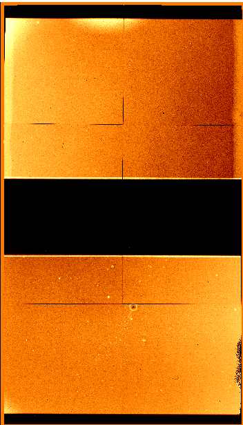
- [FYI] If there is a trouble during the mask alignment process, we may restart alignment sequence without completely storing the mask to the stocker. Or, we may try to reduce the overhead of the mask exchange by halting the MOS store sequence in the middle before going to new target. In such cases, the robot arm will stay over the FOV, and the central 350 pixel region around the mosaic boundary between channels will be blocked by it (see the example). If you can keep 4 (or more) alignment stars outside the blocked area (which would be 1415 < Y < 2095 pixel if the preimage has the dimension of [2048,3569] made by MCSRED package), you may have a benefit of reducing the overhead of re-trying MOS alignment.
|
Example of BAD alignment hole distribution. 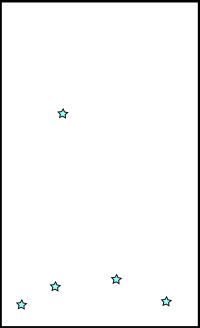 Distribution of stars are biased in the FOV. |
Example of GOOD alignment hole distribution 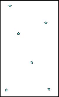 Stars are evenly distributed over entire FOV. |
3.4 Design of slits
During designing masks, you will find that several slits are close in both space (X) and dispersion (Y) directions, and are overlapping on each other. You may also find that some targets are out of the FOV, or on the detector gap. Slit design is to add/delete/modify slits to avoid such confections while searching for the best possible slit multiplex advantage.
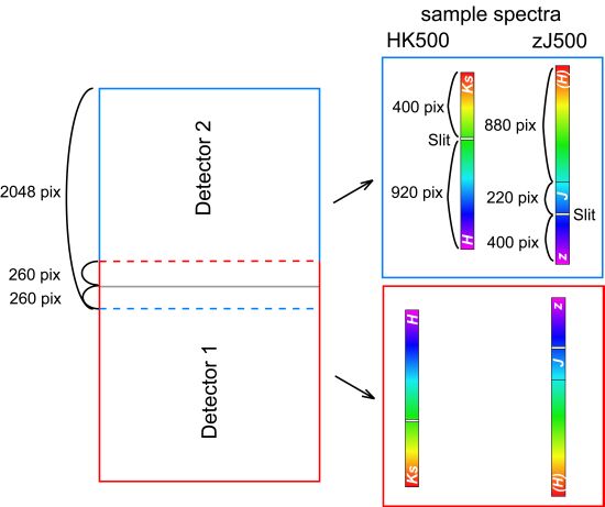
Figure: Targets can be choosen up to 2-3 arcsec close to the glued boundary of fovs between chip1 and chip2 (solid line). Spectra can be obtained about 270 pixel further than the line (red and blue dashed lines for chip 1 and 2, respectively). For example, if the spectra by a slit on chip 1 extends beyond the red dashed line, the spectra beyond the line will be terminated. The same is true for chip 2 (blue dashed line).
3.4.1 Operation
Case 1: Maual Processing
Place the slitlet information in *.mdp file manually with the format shown in 1.3.
Case 2: Interactive Processing
- Select [ Option ] - [ Change Default Slit Params ] from the pull-down menu, and input "Default Slit Width" and "Default Slit Length" in pixel unit.
e.g.) Since a pixel scale of MOIRCS is 0.117"/pix, width = 6.84 (pix) means a slit width of 0.8". For the default slit length, it is typically 70-100 pixels.
Both length and width of each slit can be modified after locating the slits. - Select a mode for the target selection at upper left of the MDP window. You may choose "pick-object" mode in which Gaussian fitting is used to find the object coordinates, or "click-point" mode in which mouse click position itself is used as the object coordinates. "Pick-object" mode is suitable for point or compact sources. For extended source the "pick-object mode" may not work properly, and in such case you can use the "click-object" mode. As the manual slit location requires the special technique to achieve a accurate positioning, the user should pay much attention to the result of the "click-object" mode. It is for diffuse and extended sources.
- Click "Add slit by click" button.
- Click on the object on the main image display. Region around the clicked position is shown on the zoom image display.
- Click on the target again on the zoom display. In "pick-object" mode, Gaussian fitting is performed around the clicked position, and the detected source is shown at the center of the zoom display as well as the rectangles for the calculated slit position. In "click point" mode, click on your favorite position on the zoom display, and the image is re-displayed around the clicked position.
- Regions occupied by the spectrum will be shown as an elongated rectangle both on the zoom and the main window. Red frames are for the spectra in the detector 1, and green frames are for the spectra in the detector 2 (the color coding may change depending on the user environment).
- Click on "Redraw" or "Draw Slit" buttons to see the updated image and the slits.
- "Newly Added Slit" comment is shown in a comment field of *.mdp file for slits which are generated interactively in the MDP program.
Tips for designing the slitlets
- Again, the objects beyond 3.0 arcminutes from the pointing center cannot be chosen as targets due to the mos mask area limitation. Avoid locating high-priority slits close to the FOV edge (should be separated by at least ~6" from the left edge: see the Note 3 above) or near the mosaic boundary (the area two channel images are glued together) closer than 6".
-
We usually use one of the suitable slitlet on one of the MOS mask you used when we observe (telluric) standard star. This is not only to save time but also to ensure to use the same flatfield data for both main target and standards during reduction. It is highly recommended to choose the suitable slitlet for the rationing star observation beforehand(*). The slit for the purpose should have the length as long as 10" or more, because we usually choose the nod throw enough wide to avoid the overlap of the wing of the spectra.
(*) Dec 2014 Update: If there is an alignment hole within ~30 arcsec from the slit for the standard star observation, it may enable us to acquire the standard star without removing the MOS mask using the autoguider (thus we can save the overhead significantly). If there is a space, you can put an empty alignment hole just adjacent to the slit for the purpose.
-
It is recommended to put slits on a bright star on each channel. The data should become useful for the quality check (flux, FWHM, etc) or the monitor of the telluric absorption during the exposure. And also, the data will enable us to measure the position or the actual nod throw length accurately, which will be effectively used for your data reduction.
-
!!! IMPORTANT !!! The spectra of some VPH grisms are tilted by 1~1.5 degree counter-clockwise with respect to the y axis. Due to this, spectra may occasionally overlapped with each other depending to the layout (see figure below). If the two adjacent slitlets are widely separated in y-direction with the left slit is up and right slit is down, the overlap will occur. Taking a margin of >15pixel per dy=1000 pixel would be better.
The tilt of the R500 grisms is reasonably small (< 0.5 degrees).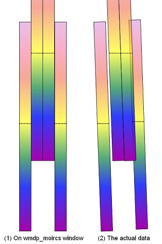
3.4.2 Check the slit/hole parameters.
There are four ways to check/modify the slit/hole parameters.
- Click the region of your interest on the main image display, and the zoom image around the selected region is shown in the zoom image display.
- Click "Show nearest slit" button and click near your interest slit on the main image display. Nearest slit is found automatically, and the zoom image around the slit is shown in the zoom image display. A small pop-up window shows the slit information as well as the slit ID selected.
- Click "Show slit(ID)" button and then input the slit ID number shown beside the slit. The zoom image around the selected slit is shown in zoom image window. A small pop-up window shows the slit information as well as the slit ID selected.
- Click "Show Slit List" button to make a slit list which displays all slit information as well as comments (if any). Radio buttons at the left of each slit ID number can be used to activate/delete slits/holes. Deleted slits/holes can be re-activated from this slit list later if you wish.
3.4.3 Adjusting/modify the slit length
You may want to reduce the slit length to avoid the slit overlapping instead of deleting slits, or expand a slit length if no targets are found around it(Note). In these cases, you can change the slit length manually.
- Click "Change Slit Params" button and click near the slit you want to modify on the main image display. The nearest slit is automatically selected.
-
Input the new slit coordinates (X coordinates of the left and right side of the slit) and/or slit width/angle in the new pop-up window.
Left = X coordinate of the left side of the slit of space direction (pixel unit)
Right = X coordinate of right side of the slit of dispersion direction (pixel unit)
Width ( PIX ) = Slit Width (pixel unit)
Angle ( DEG ) = Slit Angle (degree unit)e.g.) Since a pixel scale of MOIRCS is 0.117"/pix, width = 6.84 (pix) means a slit width of 0.8".
-
Click on "Redraw" or "Draw Slit" buttons to see the updated image and the slits.
3.4.4 Deleting slits/holes
There are two ways to delete slits/holes. Note that "delete" means "deactivate", and you may still see the slit information in the slit list to re-activate it.
Case 1
- Click "Del Nearest Slit" button.
- Click the region around the slit you want to delete on the main image display. The nearest slit is automatically selected, and deleted.
- Click "Redraw" button to see the updated slit design.
Case 2
- Click "Display Slit ID" button to see slit IDs on the image.
- Click "Show Slit List" button. A slit list will show up.
- Disable the slits you want to delete by clicking on the radio button just left of the slit. Then press "accept" button at the bottom of the list.
- Push "Redraw" button to see the updated slit design.
3.4.5 Notice Again: wmdp_moircs.sav is easy to CRASH...
As is warned already, the wmdp_moircs.sav software is known to crash fairly easily. Canceling any action would lead to the crash event in some environment. Please keep in mind that you frequently save the intermediate mdp file to avoid losing all the efforts by crash!
3.5. Saving the results
There are two types of the output data file.
First is the *.mdp file which can be used as an input of MDP program. Users are recommended to save this file frequently to avoid the unexpected loss of the information due to MDP crush etc. You can re-start the MDP program with the *.mdp file saved during the previous MDP session.
Another is the *.sbr file which is used in the slit cutting machine. Save this file after finishing the design.
3.5.1 Save *.mdp file
Select [ File ] - [ Save MDP ] from the pull-down menu. Input the file name (*.mdp), and push "OK" button.
Users are asked whether you want to keep the information on deleted slits or not in the saved file. Comments indicating "Deleted" will be added to the *.mdp file when you keep the information. This might be useful when checking the mask design later.
Sample of *.mdp file
1646.0900 2525.9802 170.0000 8.0000 0.0000 1.0000 B, Object-1
1413.2900 3187.8088 170.0000 8.0000 0.0000 1.0000 B, Object-2
1425.0000 1307.4368 150.0000 8.0000 0.0000 1.0000 B, Object-3
1596.8900 1188.6917 133.7800 8.0000 0.0000 1.0000 B, Object-4 redshift=1.2
1790.0000 1424.0500 60.0000 8.0000 10.0000 1.0000 B, Object-5 faint
1929.3048 2935.7109 30 30 0.0000 0.0000 C, Alignment Hole
1013.9686 2216.7029 30 30 0.0000 0.0000 C, Alignment Hole
1860.3289 2637.6160 30 30 0.0000 0.0000 C, Alignment Hole
1306.7455 1371.2542 30 30 0.0000 0.0000 C, Alignment Hole
2155.8694 660.0646 30 30 0.0000 0.0000 C, Alignment Hole Deleted
1840.0000 1424.0500 60.0000 8.0000 10.0000 1.0000 B, Newly Added Slit
2722.4922 2618.4399 30 30 0.0000 0.0000 C, Alignment Hole
2805.4500 1047.8396 90.0000 8.0000 10.0000 1.0000 B, Newly Added Slit
1118.0699 1456.2828 170.0000 8.0000 0.0000 1.0000 B, Newly Added Slit
3.5.2 Save *.sbr file
- Click "Draw FOV: button and write down the coordinate information (X, Y).
- Select [ File ] - [ Save SBR ] from the pull-down menu. Input the file name with an extension of *.sbr and click "OK".
-
You are asked to input the coordinate of the FOV center. The (X, Y) values you can see in the "Draw FOV" button will be shown as default values, and you do not normally have to change the values.
Note
While writing the *.sbr file, MDP checks the slit positions whether slits are out of the FOV or on the detector gap. When MDP finds any possibly wrong slits, warning messages are shown in the warning pop-up window. However, there is a known bug on the check procedure, and the warning may pop up though there is no problem in the design. You can ignore the message if there is no slit apparently outside the fov on your design.
3.6 Quitting the MDP
Select [ File ] - [ Quit ] from the pull-down menu.
Again, there may have a fake error message. Just ignore after check.
3.7 Other notes
3.7.1 Dummy slit (0th slit)
When you start the MDP without *.mdp file, a dummy slit is automatically created whose slit ID is zero (0). Delete this slit after adding other slits.
3.7.2 Coordinate system convention
MDP's coordinates start from one ( 1 ). FITS viewers such as SAOimage and Skycat also use the coordinate start from one ( 1 ), but some softwares such as IDL use the coordinate start from zero ( 0 ).
3.7.3 Care for extremely out-of-FOV slits
Slits far out of the FOV may cause a scratch on the mask holder for laser cutting machine. Though it is not dangerous, please avoid putting such wrongly-put slits. As is noted above, there is a known bug on the function of the slit position check in the software. Please ignore the warning if your mask design seems correct.
3.7.4 Changing Grism Setting Parameters
-
The ranges for HK500 and zJ500 supposes the use of the standard order-sorting filter (namely OC_HK and OC_zJ, respectively). If you use other filters for order-sorting purpose etc, you can change the graphics of spectra on display for the filter you use. Select [ Option ] - [ Grism Setting ] to set the minimum/maximam wavelength of the filter which you want to use. A frame of regions occupied by the spectrum will be changed.
-
Currently the design of the VPH grisms is not supported. However, you can make a design by appropriately setting the grism parameters. Visit the VPH grism page for the parameters to put. Note that wmdp_moircs cannot handle the displacement of the spectra from the slit position independently for channel 1 and 2. Please use the parameter separately. Please ignore the zeroth order offset. Contact the SA if you need assistance.
3.7.5 Change of Graphics
- By choosing [ Option ] - [ Preference ], you can change a color tone of the display with "color table number ( 1 - 40 )". You can also set a best resolution of the display with "demagnification factor".
4. Take a snapshot image of MDP
We ask the MDP program user to take a snapshot image of the MDP display at the end of the design. The image will be used to check the fabricated mask and be useful as a "finding chart of the alignment stars" during the MOS pointing. (rotate clockwise if you want to use it as a finding chart.)
Use your favorite snapshot software. (e.g., xv, snapshot) Any standard image formats are acceptable (such as jpg and gif).
5. Submitting the results
Submit the followings to the support scientist. E-mail submission is preferable.
* *.mdp file
* *.sbr file
* snapshot image of MDP display
* The XY coordinates of the FOV center (the FOV Center value used to generate the sbr file)
When you prepare the OPE file for your MOS observation, make sure to specify the RA/DEC value of the FOV center (not the main target position!). For the FOV center you can use either the center of the yellow rectangular box on MDP window (MOIRCS FOV) or the center FOV which you used to generate the sbr file. Either will work (i.e., this level of accuracy is enough).
6. Acknowledgment
We deeply appreciate Dr. Takashi Hattori for his efforts to revise the original MDP software for the application to MOIRCS. We also thank to the FOCAS Team, who have developed the original MDP software. This manual is written based on the MDP manual for FOCAS.
Document Preparation by Chihiro Tokoku (July 2006) / Revised by Ichi Tanaka