System Overview of Subaru AO188
AO188 module
Subaru AO188 is an 188-element curvature sensor adaptive optics system that is operated in both natural guide star (NGS) and laser guide star (LGS) modes. AO188 module is mounted on the Nasmyth platform as shown in Fig 1.
The system is based on a curvature wavefront sensor. The bimorph deformable mirror (DM) used until May 2024 had 188 sub-apertures, and has been upgraded to a new 3228-actuator magnetic deformable mirror.
It is the highest correction order of the curvature sensor AO system. The optics of AO188 is mounted on the 1.72 x 2.1 m optical bench (see Fig 2). The field of view of the optics covers 2.7 arcmin of the sky. We use this wide field optics mainly to acquire tilt guide stars for laser guide star operations. Calibration light sources which generate both natural guide star light and laser guide star light with turbulence plates that can mimic the atmospheric turbulence are installed. An image rotator unit is also installed on the AO optical bench. The detail specification of the AO188 is summarized in Table 1.
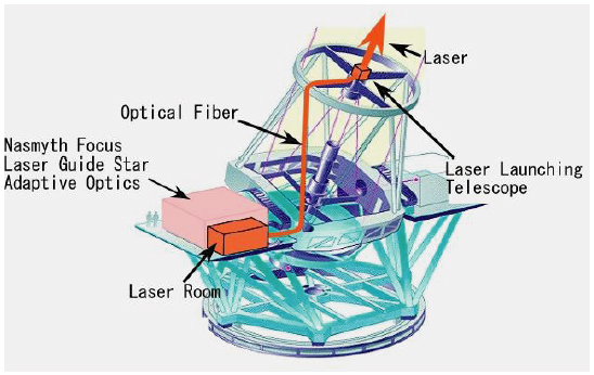
Fig.1 Overview of the Subaru laser guide star AO system. This figure shows the system based on the old laser system. The new laser system uses optics composed of mirrors instead of the fiber.
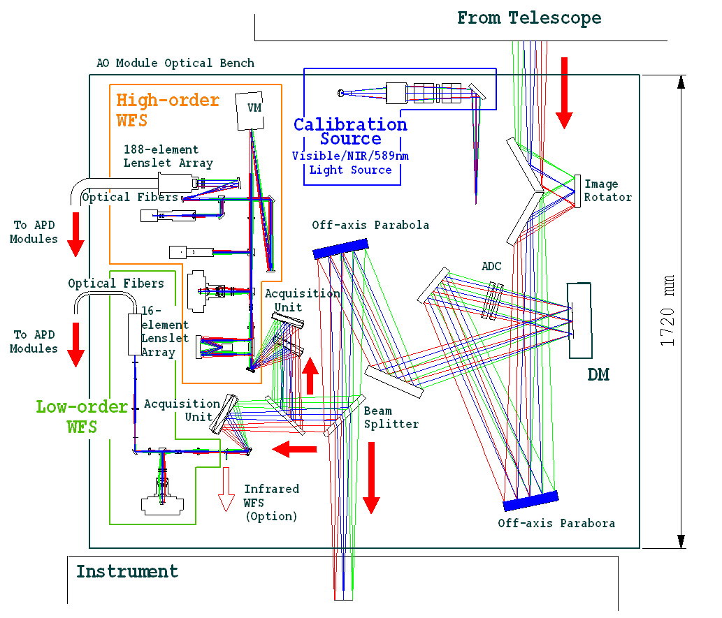
Fig.2 Optical bench layout of AO188
- Reference
- "Design of the Subaru laser guide star adaptive optics module"
Watanabe et al. 2004, Proc. of SPIE, 5490, 1096
- "Design of the Subaru laser guide star adaptive optics module"
Image rotator
A K-type image rotator (IMR) that consists of three flat mirrors mounted on a rotation stage is used to track parallactic angle. Currently, following tracking modes are available.
- Field rotation tracking for sidereal and non-sidereal objects
- Pupil rotation tracking for sidereal objects (so-called ADI mode)
- No tracking (stop IMR rotation)
The pupil rotation tracking mode for non-Sidereal objects will be implemented soon.
Atmospheric dispersion corrector
An atmospheric dispersion corrector (ADC) is installed in the science path of AO188. It has a conventional design, which consists of two identical doublet prisms. This ADC corrects the atmospheric dispersion in both visible and infrared wavelength over 0.45-2.2 μm for both science instrument and wavefront sensors. When the zenith angle is small and the correction is not needed for the science instrument, the science-path ADC can be removed and other ADCs in the WFSs are used for the correction in the visible wavelength. Field and pupil tracking modes for sidereal objects are available. If you want to use the ADC for non-sidereal objects, please contact the support astronomer.
- Reference
- "Atmospheric dispersion correction for the Subaru AO system"
Egner et al. 2010, Proc. of SPIE in press
- "Atmospheric dispersion correction for the Subaru AO system"
Deformable mirror
A new 3228-actuator magnetic deformable mirror (DM) manufactured by ALPAO was installed in 2024. The 3228 actuators are distributed on a 64 x 64 regular square pattern across a circular full aperture of 96mm with a pupil size of 93.5mm. The tip-tilt mount that was combined with the 188-element DM will be relocated to the M2 mirror of the AO188 to correct the accumulated tip/tilt error.
- References
- "AO3000 at Subaru: Combining for the first time a NIR WFS using First Light's C-RED ONE and ALPAO's 64x64 DM"
Lozi et al. 2022, Proc. SPIE, vol. 12185, id. 1218533 - "Tests and characterisations of the ALPAO 64x64 deformable mirror, the MICADO-MAORY SCAO AIT facility"
Vidal et al. 2019, Proceedings of the AO4ELT6 conference, E4
- "AO3000 at Subaru: Combining for the first time a NIR WFS using First Light's C-RED ONE and ALPAO's 64x64 DM"
Before the installation of the 3228-actuator DM, a 188-element bimorph type deformable mirror (DM) that was manufactured by CILAS was used. The bimorph mirror is made of two PZT plates with a diameter of 130 mm (beam size 90 mm) and a total thickness of about 1.9 mm. Control electrodes are located between the two plates. This DM was mounted on a tip/tilt mount to correct a tip/tilt error accumulated on the DM.
- Reference
- "Performance of the deformable mirror for Subaru LGSAO"
Oya et al. 2006, Proc. of SPIE, vol. 6272
- "Performance of the deformable mirror for Subaru LGSAO"
Beam splitter
Two kinds of beam splitters called BS1 and BS2 are installed in AO188. BS1 is used to split the input beam into two beams for the wavefront sensor and science camera. Currently, we have two BS1s with different cut-off wavelengths of 900 nm and 640 nm for using NIR (IRCS and HiCIAO) and optical (Kyoto-3DII) science instruments. For the BS2, a flat mirror is used for the NGS mode to reflect the input beam toward the high-order wavefront sensor (HOWFS) and a notch filter that reflects only 589 nm light toward the HOWFS and transparents light of other wavelengths to feed a laser guide star to the HOWFS and a tip/tilt guide star to the low-order wavefront sensor (LOWFS). All beam splitters are installed in the BS automatic exchanger units that allow to switch observation mode easily during a night.
- Reference
- "Development of a dichroic beam splitter for Subaru AO188"
Minowa et al. 2008, Proc. of SPIE, vol. 7015
- "Development of a dichroic beam splitter for Subaru AO188"
Guide star acquisition unit
To feed a guide star to the wavefront sensor, we are using a guide star acquisition unit that consists of two gimbal mirrors and a linear stage. The gimbal mirrors adjust the position and ray tilt of the guide star. The linear stage is mounted under the one of the gimbal mirrors and adjusts the focus position of the guide star by changing the separation of two mirrors. There are two acquisition units called AU1 and AU2 for acquiring a guide star for the high-order and low-order wavefront sensors, respectively. AU1 acquires a LGS or NGS within a FOV of 2 arcmin, while the AU2 acquires a Tip/Tilt guide star within a FOV of 2.7 arcmin.
High order wavefront sensor
The high-order WFS is a visible 188-element curvature based wavefront sensor with photon counting APD modules, and measures high-order terms of the wavefront using either a single LGS or NGS. It basically consists of a fast tip/tilt mirror with an Offner relay to stop the LGS image at the focus, relay lenses to convert the focal ratio, an ADC for the NGS beam, a vibrating membrane mirror (VM), collimating mirrors, a lenslet array coupling to APDs through optical fibers, an acquisition CCD camera with a 20 arcsec FOV, a high-resolution camera with a pixel scale of a few milli-arcsec, and a pupil camera.
- Reference
- "Implementation of 188-element Curvature-based Wavefront Sensor and Calibration Source Unit for the Subaru LGSAO System"
Watanabe et al. 2008, Proc. of SPIE, vol. 7015
- "Implementation of 188-element Curvature-based Wavefront Sensor and Calibration Source Unit for the Subaru LGSAO System"
Low order wavefront sensor
For the LGS mode operation, we also need a natural guide star wavefront sensor (LOWFS) to measure wavefront tilt and defocus, which is not measured by the laser guide star spot. Those stars for tilt measurement can be fainter than the magnitude required for HOWFS. We use 2 x 2 Shack-Hartmann (SH) wavefront sensor to measure the wavefront tip/tilt and defocus using 16 photon counting APDs. It has a slightly lower throughput compared to the SH sensor with CCD, however it is adequate for fainter guide stars because it uses zero readout noise APDs. The LOWFS basically consists of relay lenses to convert the focal ratio, an ADC, a collimating lens, a 2x2 sub-aperture SH lenslet array, and a 4x4 lenslet array which connects to 16 APDs through optical fibers. It also has an acquisition CCD camera with a FOV of 20 arcsec and a pupil camera for field acquisition and alignment.
- Reference
- "Visible Low-order Wavefront Sensor for the Subaru LGSAO System"
Watanabe et al. 2010, Proc. of SPIE in press
- "Visible Low-order Wavefront Sensor for the Subaru LGSAO System"
Laser guide star system
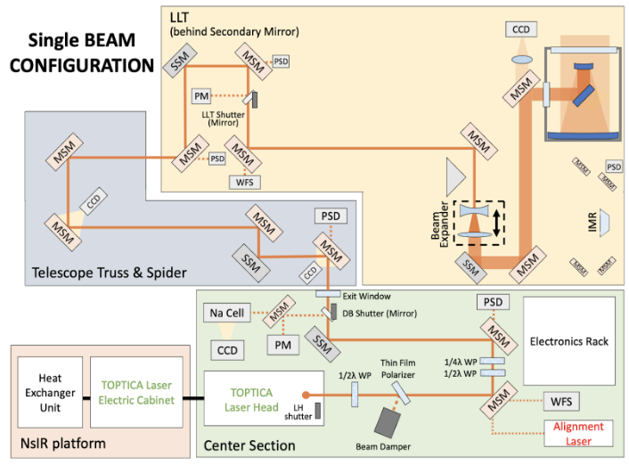
The figure above shows schematic diagrams for the new laser guide star system (from S23A semester) for AO188. The TOPTICA laser system consists of an Electric Cabinet (EC) and a Laser Head (LH). The EC is located at the Nasmyth IR platform. Pump and seed infrared laser beams are generated and transferred to the LH at the center section through optical fibers. At the LH, the seed laser beam is amplified and frequency doubled to emit a 589 nm laser beam with a diameter of 3 mm into the air. At the exit of the LH, there is a shutter (LH shutter). When the shutter is closed, the laser beam is fully absorbed in a water-cooled beam damper located in the LH. When the LH shutter is opened, the 589 nm laser beam is transferred to the Laser Launching Telescope (LLT) located behind the telescope secondary mirror through a diagnostic bench (DB) at the center section and a relay system along the telescope truss and spider.
The DB has four functions: laser beam diagnostics, laser beam power adjustment, laser beam polarization state manipulation, and laser beam alignment compensation. The laser beam alignment stability, wavefront distortion, power, and wavelength are measured using a position sensitive device (PSD), a wavefront sensor (WFS), power meter (PM), and Sodium gas cell (Na cell), respectively. The laser beam power transferred to the downstream of the DB can be adjusted in between ~2 W and ~23 W by rotating a half-waveplate (WP) located just after the LH exit. The half-WP can change the angle of linear polarization and then change the fraction of the laser beam power reflected by a thin film polarizer (TFP) toward a water-cooled beam damper on the DB. After the TFP, the beam polarization state can be further manipulated by the combination of a half-WP and a quarter-WP so that the final laser beam propagated from the LLT toward the sky is circularly polarized, which maximize the return photons from a Sodium layer at the mesosphere. The DB has an exit shutter (DB shutter) to block the laser beam in the DB so as not to transfer the laser beam toward the downstream relay system. When the CS DB shutter is closed, the laser beam is reflected toward a water-cooled power meter (PM).
When the DB shutter is opened, the laser beam is transferred toward the LLT through the relay system along the telescope truss and the spider. In the relay system, there is a PSD and a slow steering mirror (SSM) to measure and compensate for the mis-alignment of the laser beam because of the telescope deflection in combination with another SSM on the DB. In the relay system, there are two CCD cameras monitoring the laser beam location on the mirrors (manual steering mirror: MSM) to provide additional data to estimate the beam mis-alignment.
In the LLT, there are PSDs and a SSM just after the entrance to measure and compensate for the mis-alignemnt of the laser beam between the relay system and the LLT. A laser shutter (LLT shutter) is located after the second PSD to block the laser beam in the LLT. When the LLT shutter is closed, the laser beam is reflected toward an air-cooled PM. When the LLT shutter is opened, the laser beam is propagated on-sky through the downstream optical system. The laser beam is directly transferred to a beam expander (BE) where the laser beam is 6x magnified and then transferred to the launching telescope where the beam is further magnified by a factor of 12. The final beam size propagated on sky is ~220 mm in 1/e2 diameter.
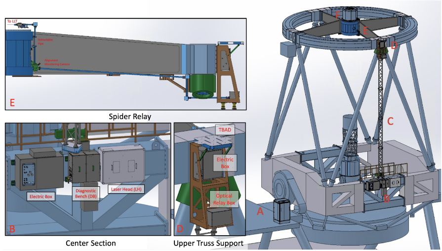
The figure above shows a 3D model of the entire laser guide star system installed on the telescope. The laser guide star system mainly consists of the following components:
A. TOPTICA electric cabinet (EC) on the Nasmyth IR platform,
B. TOPTICA Laser Head (LH) and Diagnostic Bench (DB) on the front side of the center section,
C. Laser relay truss between the center section and the top ring,
D. Laser Steering Mirrors and TBAD (aircraft detector) at the front side of the top ring,
E. Relay pipe along the front side spider,
F. Launching telescope behind the secondary mirror.
Old laser guide star system
The old laser system was installed at the Nasmyth floor next to the AO188 optical bench, a sum-frequency solid state 589nm laser with average 6.8 W output power. The laser beam was transferred to the laser launching telescope through a single mode photonic crystal fiber with a 14 micron core diameter. The overall throughput for the laser transfer fiber and optics was about 60% and then the on-sky output power is 4.0W which corresponds to 10.5 mag (at zenith) in R band.
- References
- "The laser guide star facility for Subaru Telescope"
Hayano et al. 2006, Proc. of SPIE vol. 6272 - "589 nm sum-frequency generation laser for the LGS/AO of Subaru Telescope"
Saito et al. 2006, Proc. of SPIE vol. 6272 - "High-Power Laser Beam Transfer through Optical Relay Fibers for a Laser Guide Adaptive Optics System"
Ito et al. 2009, PASJ, 61, 763
- "The laser guide star facility for Subaru Telescope"
updated on August 01, 2024