Information for PIs
Further information
Questions regarding this page should be directed to Naoyuki Tamura.Proposal checklist
- There are three observing modes available and the main differences are summarized in a table below. Have you chosen one for your observation with them considered?
- [Operational mode] From S12A, the High Resolution mode (HR) as well as the Low Resolution mode (LR) will be available on both IRS1 and IRS2. In S11B, LR will be available on both IRS1 and IRS2, while HR will be in operation only on IRS1.
- [Number of fibers] There are 12 fibers that are not available for observation of science target, mainly because the spines move not well enough (so most of them are still useful to take sky spectra). Therefore the total number of fibers available to observe science target is 388.
- [High Resolution mode] In the operation of
HR, a few important restrictions will be applied. Applicants should
take the following notes into account in making proposals:
- The FMOS spectral coverage (0.9-1.8 um) is divided into four bands in HR: J-short (0.90-1.16 μm), J-long (1.09-1.35 μm), H-short (1.40-1.66 μm) & H-long (1.54-1.80 μm), and one of them is covered by a single exposure. HR observation is carried out by using these pre-defined bands only. Note: More flexible operation may be possible in future semesters, but as of Feb 2011 more engineering works will be necessary to do so. Hence we decided to apply the restriction in S11B (i.e. the first semester of HR open-use) to minimize any technical risks.
- To minimize the risk of increasing additional overhead, observers need to keep the same setting of IRS1 from beginning to end of a night - i.e. no change is allowed in observation mode (e.g. LR → HR, HR → HR but a difference band) during a night.
- It would be acceptable to use IRS1 and IRS2 in different observation modes (e.g. LR in IRS1 and J-long in IRS2), while it is strongly recommended to plan to use IRS1 and IRS2 in the same mode to accurately position Echidna spines/fibers: Due to the effects of atmospheric dispersion and chromatic aberration, the position of an object on the focal plane is slightly different as a function of wavelength, and the spine-to-object (s2o) allocation software cannot allocate spines according to different requests (e.g. observation wavelength) to spines for IRS1 and those for IRS2. This means, if one tried observation in J-long with IRS1 and in H-long with IRS2 and set observation wavelength for spine allocation to 1.3 μm, less flux would fall into the fiber for the H-long observation.
- [Overhead estimation] Have you calculated the
total amount of time to request with taking overhead into
account appropriately? Typically, ~20 minutes is necessary for
telescope pointing, dome rotation, Echidna spine configuration, target
field acquisition, and focusing. In addition, for long
integration, Echidna spine re-configuration which takes ~10
minutes is necessary every ~30 minutes. Resultantly, the
typical observation efficiency in long integration is ~60%
(i.e. the overhead is ~40%).
[See this page for more details.] - [Magnitude zeropoint] If you justify on-source integration time based on a certain magnitude in the proposal, have you clarified which zeropoint, Vega or AB, should be applied to the magnitude? In NIR, the difference between Vega mag and AB mag against a given flux density is 1-2 mag, which is significant.
- [Guide stars and coordinate calibration
stars] In the target fields, are there a number of bright stars
suitable for guide stars (R = 12-16 mag) & coordinate
calibration stars (R = 12-15 mag) with accurate relative
astrometry to science targets?
[See this page for more details.] - [OH mask] Is the spectroscopic feature you need to observe expected to be robust enough against the effect of OH masks? You can check the list of OH masks here. Also, FMOS spectrum simulator may be helpful to see the effect.
| Observing mode | Fraction of fibers for science targets |
Fraction of on-source integration time (1) |
Fraction of on-source integration time (2) |
|---|---|---|---|
| Normal beam switching | ~100% | 50% | ~30% |
| Cross beam switching | ~50% | 100% | ~60% |
| Point & stare | ~80-90% | 100% | ~60% |
(2): This percentage represents 100 x ([On-source Integration Time]) / [Total Observing Time (including overhead)]).
Observation checklist
- [Operational mode] In S11B, LR will be available on both IRS1 and IRS2, while HR will be in operation only on IRS1. From S12A, HR as well as LR will be available on both IRS1 and IRS2.
- [S2O file submission] Have you sent S2O
file(s) to the support astronomer
(Kentaro Aoki
 )? If you observe more
than one spine allocations/target fields, please send all the
corresponding S2O files. If you saw any error messages or warnings in
making the S2O file(s), please consult well before your
observation.
)? If you observe more
than one spine allocations/target fields, please send all the
corresponding S2O files. If you saw any error messages or warnings in
making the S2O file(s), please consult well before your
observation. - [S2O file name convention] Did you name the
S2O files following the format
"PROPOSALID_PILASTNAME_ANYCOMMENT_OBS.s2o"? In the
"ANYCOMMENT" part, observers can choose a useful phrase to classify
the file (e.g. name of target field). "OBS" should be replaced with
one of "nbs", "cbs", or "pas" depending on the selected observing
method: Normal Beam Switching, Cross Beam Switching, or Point & Stare,
respectively (see this page for the
details of the observing methods). For example, if your proposal ID is
S10A-000 by PI: Tamura and you observe a target field named
"somewhere" by cross beam swiching, then please name the S2O file as
"s10a_000_tamura_somewhere_cbs.s2o".
NOTE: The S2O file names should be CASE-INSENSITIVE, i.e., you should NOT mix lower-case and upper-case characters in the file name.
- [OPE file submission] Have you sent an OPE
file to the support astronomer
(Kentaro Aoki )? Are the target
information and the names of S2O files correct? Did you name the OPE
file following the format "PROPOSALID_PILASTNAME.ope"? For
example, if your proposal ID is S10A-000 by PI: Tamura, then the name
of an OPE file would be "S10A_000_TAMURA.ope".
[See also this section. for some details of OPE file.] - [Guide stars] Did you manage to have two or more guide stars on the guide fiber bundles (NOTE: Two bundles are currently unavailable due to their less good positioning cababilities - see this page)? Are they bright (R = 12 - 16 mag) and on the same astrometric system as science targets? Observers firstly should try to choose field center and position angle (PA) to maximize the number of available guide stars, with one or more guide stars available on each row (but, there is one technical restriction in choice of PA - see the next item). The more guide stars are available, the more stable AG operation is expected. Especially, the operation should be rubust against unexpected contamination of stars with large proper motions, double stars, those with large errors in astrometry, magnitude, etc. In addition, if many GS are bright, the exposure time for AG could be shortened. Then telescope pointing correction could be applied at a shorter interval and subsequently guiding error could be smaller.
- [Position angle] In the spine allocation, observers need to choose a PA. For a long interation across the transit in the southern (northern) sky, it is better to set PA somewhere around 0 deg (180 deg), respectively. (In fact, 0±90 deg (180±90 deg) is acceptable). This is due to the specification of the rotator in the Prime Focus unit for IR (PIR, used by FMOS), which can go only from -180 deg to +180 deg. Hence, if you set PA to 180 deg to observe southern sky, for example, the rotator comes to 180 deg at the transit and stops there due to the limit. For another example, if you set PA to a value large in negative (e.g. -150 deg) and try to observe southern sky right after it rises, the rotator may hit on the negative limit. If this happens in the middle of an exposure, this data frame is unlikely to be very useful. Also, an additional overhead occurs to get the rotator back to -180 deg (or the other way) and restart the tracking.
- [Coordinate calibration stars] How
many coordinate calibration stars are available in your S2O
file? Are they bright (R = 12 - 16 mag) and on the same
astrometric system as science targets? Observers are recommneded
to prepare at least one CCS near the field center and a few stars
surrounding it in the outer field to calculate not only lateral
offset to telescope pointing but also rotational offset to instrument
rotator. Observers may leave many CCS available in S2O files. Although
the actual field acquisition is performed by using ∼ 5 CCS, if
more CCS are available in an S2O file then the instrument control
system picks up several from them considering the positions in the
FoV.
The CCS near the center of FoV is also used for focusing operation. If a star at a distance larger than 10 arcmin from the center of the FoV is used for focusing operation, the focus value derived could be less accurate due to the effect of curvature of focal plane.
- [Brightness of guide star and coordinate calibration star] Please make sure, GS and CCS are bright enough in the R band. Please be aware that the "R" band in the UCAC3 catalog is somewhat different from the standard R band (see this section). Also note that FMOS is a near-infrared spectrograph, but the guide camera and SKYcamera are CCD cameras for visible wavelengths.
- [Several fibers showing throughput variation]
The throughput of 11 fibers fed to IRS1 and 3 fibers to IRS2 seems to
vary with time by a few percent and the amount of this variation is
different as a function of wavelength. Observers should confirm that
these fibers are not allocated to stars for telluric absorption
correction and flux calibration (at least spectra from these fibers
should not be used for such purposes).
[See this page for more details.] - [Ghost feature] Are there any spines allocated on very bright objects (e.g. 13 mag or brighter), while much fainter objects will be observed simultaneously? Brighter objects would make brigher ghost features on the detector, which could affect the spectra of fainter objects. Empirically, a ghost feature appears at a three-orders-of-magnitude (i.e. 7.5 mag) fainter level than the original brightness. For example, if you observe a star of 13 mag, a ghost feature would appear on the detector with a brightness of 20.5 mag, which may be unacceptable for the spectra of objects of ∼ 18 mag or fainter in the same exposure, depending on the goal of the observation.
- [Overhead estimation] Please remember to take overhead into account appropriately. Typically ~20 minutes is necessary for target acquisition, including telescope pointing, dome rotation, focusing, and Echidna spine configuration. In addition, for long integration, Echidna spine re-configuration which takes ~10 minutes is necessary every ~30 minutes. Resultantly, the typical observation efficiency in long integration is ~60% (i.e. the overhead is ~40%).
- [High Resolution mode] In the operation of
HR, a few important restrictions will be applied. Applicants should
take the following notes into account in making proposals:
- The FMOS spectral coverage (0.9-1.8 um) is divided into four bands in HR: J-short (0.90-1.16 μm), J-long (1.09-1.35 μm), H-short (1.40-1.66 μm) & H-long (1.54-1.80 μm), and one of them is covered by a single exposure. HR observation is carried out by using these pre-defined bands only. Note: More flexible operation may be possible in future semesters, but as of Aug 2011 more engineering works will be necessary to do so. Hence we decided to apply the restriction in S11B (i.e. the first semester of HR open-use) to minimize any technical risks.
- To minimize the risk of increasing additional overhead, observers need to keep the same setting of IRS1 from beginning to end of a night - i.e. no change is allowed in observation mode (e.g. LR → HR, HR → HR but a difference band) during a night.
- It would be acceptable to use IRS1 and IRS2 in different observation modes (e.g. LR in IRS1 and J-long in IRS2), while it is strongly recommended to use IRS1 and IRS2 in the same mode to accurately position Echidna spines/fibers: Due to the effects of atmospheric dispersion and chromatic aberration, the position of an object on the focal plane is slightly different as a function of wavelength, and the spine-to-object (s2o) allocation software cannot allocate spines according to different requests (e.g. observation wavelength) to spines for IRS1 and those for IRS2. This means, if one tried observation in J-long with IRS1 and in H-long with IRS2 and set observation wavelength for spine allocation to 1.3 μm, less flux would fall into the fiber for the H-long observation.
Please refer also to this page. Ghost feature tends to appear just below the spectrum of a bright object.
Preparation of an OPE file
- What is OPE file?
- How is it used?
- Template OPE file
Observation Procedure Execution (OPE) file contains a list of abstract commands to operate the telescope and instrument in actual observations. Like the other instuments on Subaru, observers using FMOS will also need to prepare an OPE file according to their plans of data acquisition during a night. Target information, observing method, exposure time, and so on will also need to be specified in this file.
In an actual observation, the content of an OPE file is displayed on the main telescope system control GUI. A support astronomer or telescope operator then selects the line of a certain command in it (with parameters in many cases) to execute when necessary. Observations proceed usually by repeating this for different commands.
Although an OPE file can be edited on the GUI during a night, to minimize overhead, it is important for observers to provide all the target information and prepare all the commands in OPE files that are used in their observations. On the other hand, since a command is manually picked up from an OPE file and is executed one by one, it is not extremely important to organize the commands exactly along the time sequence in an OPE file.
A template of OPE file for FMOS observation is available here:
Observers will need to download the text version of template and edit it to make one for your observation. Please refer to the PDF version as a brief manual. Then it needs to be sent to support astronomer(s) for FMOS open-use observations (Kentaro Aoki
).For clarity, please name your OPE file following the format "PROPOSALID_PILASTNAME.ope". For example, if your proposal ID is S10A-000 by PI: Tamura, then the name of an OPE file should be "S10A_000_TAMURA.ope".
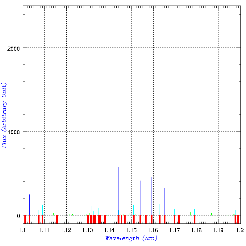
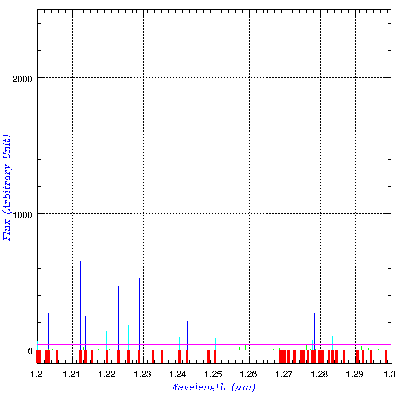
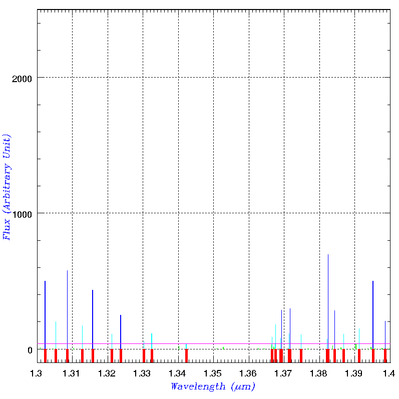
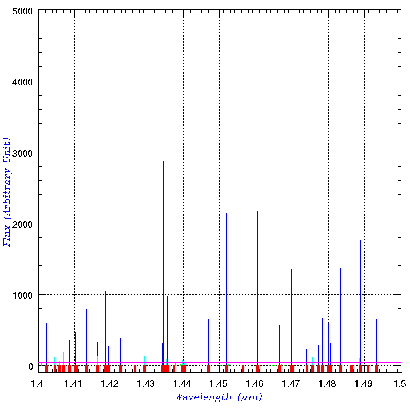
List of OH airglow masks
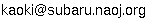
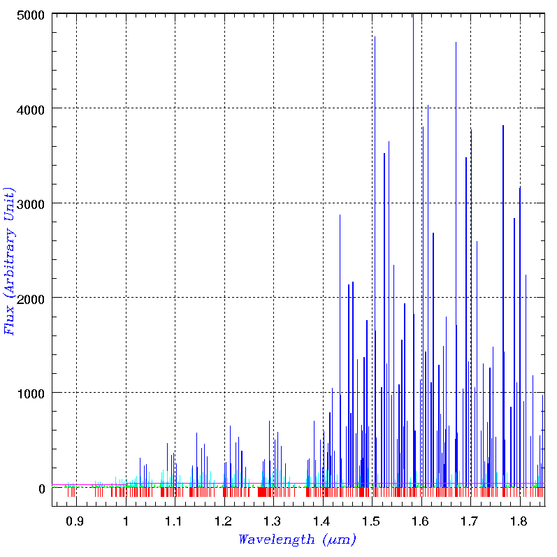
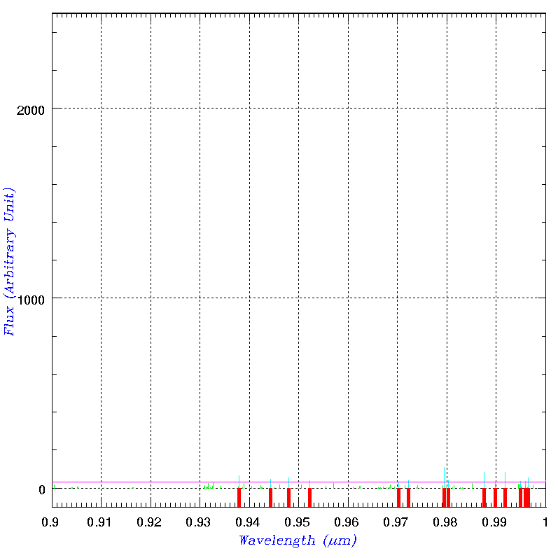
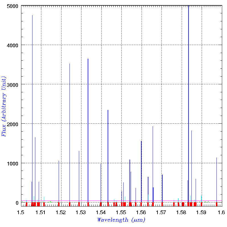
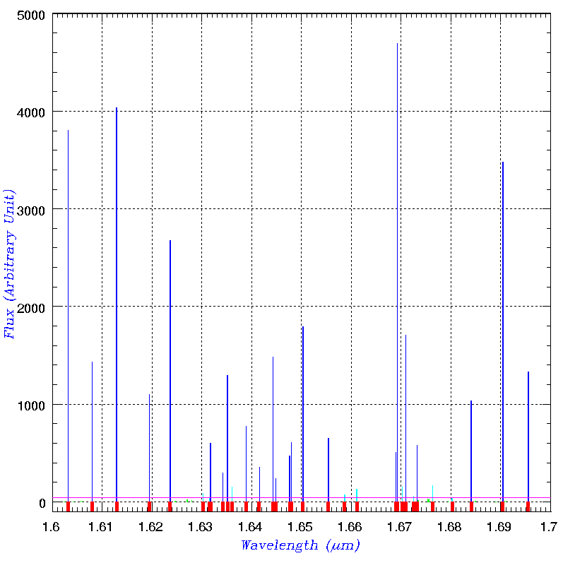
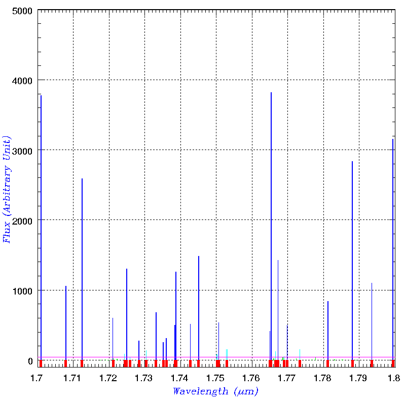
Based on the list of OH-airglow lines by Rousselot et al.(2000, A&A, 354, 1134), those to be masked were determined. The list of the masked lines can be retrieved from here. The width of each mask line is 8Å. Note that there is no mask between ~1.35μm and ~1.40μm because no spectral information is available at these wavelengths due to the presence of the fiber slit.
The figures below show the locations of OH-airglow lines and masks adopted in the FMOS spectrograph. The top left panel shows the entire spectral coverage of FMOS (0.9μm-1.8μm), while the others indicate the details by dividing it into 9 pieces (i.e. 0.1μm sampling). The following information is color-coded in these panels:
- Blue - These OH lines are masked.
- Cyan - Same as blue, but weaker lines are indicated.
- Green (barely visible in this figure around the zero level) - These OH lines are NOT masked.
- Red - Locations of the OH masks adopted on FMOS.
- Magenta - The solid line along the horizontal axis indicates the threshold to the brightness of OH-airglow lines. The OH masks on FMOS were designed to block those brighter than this threshold.
Echidna spine ID and spectrum ID match-up
Below is a list of match-up between Echidna spine IDs on the focal plane (you can see them on the spine allocation software) and spectrum IDs on the detector. To the spectra, the numbers of 1-200 are assigend in the ascending order from bottom to top of the detector (i.e. from 1 to 2048 in y-axis).
FIBRE-pac: FMOS data reduction package
In the series of engineering observations, we have been developing a data reduction & calibration package ( "FIBRE-pac: FMOS Image-Based REduction Package", Iwamuro et al. 2011, PASJ in press, arXiv.1111.6746). This consists of IRAF tasks and C programs using the CFITSIO library that are excuted from a command line on a Linux or Mac OS X. This software package has been used to reduce and calibrate the data from recent observations including those of open use. After a long period for optimization, bug-fix, and verification, it has almost reached to a stable version. Please go to the web site below to download the package. A manual and training data set are also available.
- FIBRE-pac: FMOS Image-Based REduction Package:
Last updated: Jan 30, 2012
Copyright�D 2000-2011 Subaru Telescope, NAOJ. All rights reserved.